Adjustable bottom ball joints
Traction Owner’s Club › Forums › Technical › Suspension & steering › Adjustable bottom ball joints
- This topic has 3 replies, 3 voices, and was last updated 7 years ago by Peter Fereday.
-
AuthorPosts
-
30th April 2018 at 5:12 pm #22765
Peter Fereday
ParticipantJust received a pair of bottom ball joint adjusters from Franssen, don’t seem to be available from the club shop although I may be wrong – the club tools guide mentions TOC part number H4, but the on-line parts list has that as a ‘steering’ ball joint adjuster??? Confusing or what?
Any way I’ve bought them now – my question is how do you fit them? I had the bottom ball joints off the car two years ago when replacing the brake drums and driveshafts – that’s another story – so I know how they’re made up. What I really want to know is what do you leave out – is it just the shims?? There seems to be be some debate about spacers etc…… I would really appreciate a blow by blow account of how to do it if possible. I can even respond to part numbers if required, such is the sadness of this old gits life.
Thanks
Peter
 30th April 2018 at 11:47 pm #22766
Chris
ParticipantPeter,
According to Chris Ryle’s 1999 article, reprinted in F-P Vol 41 Iss 4, pp 28-9, you discard the shims.
https://traction-owners.co.uk/wp-content/uploads/2017/09/FP-Vol-41-Iss4.pdf
Chris
1st May 2018 at 11:15 am #22767Bernie
ParticipantPeter,
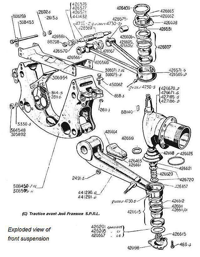
It is imperative that you retain everything but the shims, (426201, 203 and 667), and the bottom cover plate (426198). The ball assembly does not have to be disturbed.
The adjuster merely eliminates the (awkward) process of shimming. It should only be used with a good condition set of cups, spacer and ball because it is neither designed nor capable of taking up wear.
The difficulty in assembly with this – as with the original shims – is that, with the vehicle supported on the jacking point of the lower arm, when the bottom cover plate is released the hub unit tends to descend into the lower socket under its own weight.
I therefore recommend holding the upper wishbone and the lower arm apart with a jack or similar before even removing the three screws holding the bottom cover plate and then keep them locked apart during reassembly to enable the components to be replaced without having to fight the weight of the hub whilst the parts are clamped up.
Once the adjuster is firmly fixed in position with the three screws the central “adjusting” screw should be tightened fully to ensure the ball/cup/spacer assembly is correctly seated within the lower arm with the spacer ring securely clamped between the two cups so that the later cannot move and cause wear to the housing.
Hope this helps – but ask if you want more detail.
B…………….
1st May 2018 at 6:25 pm #22770ParticipantThanks for all this brilliant info, exactly what I needed. Will report back when job done.
Peter
-
AuthorPosts
- You must be logged in to reply to this topic.