Fuel Gauge
Traction Owner’s Club › Forums › Technical › Electrics › Fuel Gauge
- This topic has 11 replies, 4 voices, and was last updated 7 years, 1 month ago by David Faulkner.
-
AuthorPosts
-
7th April 2018 at 11:13 pm #22670
Roger Grix
ParticipantHi.
1955 Light 15.
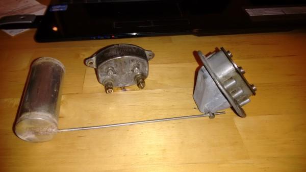
My fuel gauge is not working and I am fiddling with it. I have the pointer moving a bit but, clearly the unit needs calibrating. Does anyone have any instructions regarding calibration of the gauge? I have established that the gauge contains 2 coils. Both coils seem to have a fixed excitation in series from the ignition switch. In addition, one has a variable component controlled by the tank sender unit. The two coils work in opposition to one another to give a variable reading.
Both coils are mounted on movable fixings and, I assume, one can set the zero and full scale deflection by juggling the coil positions. Knowing the correct values for the sender resistance (max/min) would be a help but at the moment it is all a bit hit and miss. I will remove the sender tomorrow and check the values but I don’y know if mine is correct anyway.
Too many variables – not enough information.
I have some information from MG and Austin 7 clubs which I will try to insert but I am not hopeful. (Failed – don’t know how to attach a .pdf)
I think I have seen something recently either on the forum or in FP but can’t remember where.
Roger
8th April 2018 at 2:30 pm #22672Chris
ParticipantRoger,
Back in 2014 there was some discussion on this forum which points to Floating Power, Volume 28, Issue Number 5 (Nov / Dec 2004) – page 14 and 15 have an article by Alec Bilney on this topic which should cover what you need.
Chris
8th April 2018 at 2:59 pm #22673David Selfridge
ParticipantHi Roger
I cured my car (1938) by making a Dipstick and carrying it in the boot, sorry not much help technically. Seemingly you can not get a Sender for a prewar car, just not available. About a year ago Chris from TOC Spares said he was working to try and resolve by modifying a similar sender from an old Austin.
Not much help (useless I guess) but thought I’d share anyway
Davy
8th April 2018 at 3:44 pm #22674David Faulkner
ParticipantMy gauge (French Car) is ‘unpredictable’ so I simply reset the trip meter when I fill up and at circa 250 kms know I need to fill up…..
8th April 2018 at 6:01 pm #22675ParticipantI do exactly the same! And I start sweating at 280 km if I have forgotten to fill the spare can up after mowing the lawn.
Chris
9th April 2018 at 7:47 am #22676ParticipantThank you all for the feedback. I currently have a high-tech dipstick (Heh heh, I told them I’ve already got one, said with a French accent). However, being an electrical engineer, I do feel morally bound to make the electrical system work. 🙂
Following up on Chris’s reference to Alec Bilney’s article and from that to Steve Reed’s 2003 article, one thing has become very clear – not all petrol gauges and senders are created equal. The basic principles apply but the number of connections and arrangement of the sender differ. Mine has no damper and only one terminal.Similarly, the resistances seem to vary depending on the model. Measuring from terminal B to terminal T gives a resistance of 60 ohms for the B coil. Measuring from terminal T to the case (earth) gives 100 ohms for the T coil. The sender variable resistor is about 1 ohm (Empty) and 86 ohms (Full).
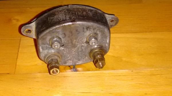
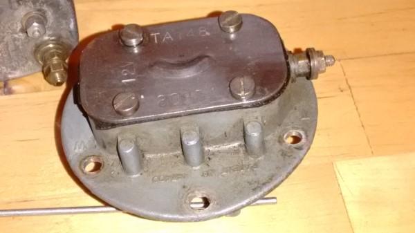
On the back of the meter there are the two terminals (B & T) and two small nuts on studs that are in slotted holes. This allows the coils to be move closer to or further from the needle armature to give each coil a variable effect on the needle movement. This should, I think, allow the setting of max and zero positions for full and empty.
With all the bits on my desk and a 12V power supply, I have so far managed to fiddle the coils to give me a range between about 1/8 to full tank indication. I am battling to get it to come to zero with the sender fully down. I’ll see what I can achieve today.
 9th April 2018 at 11:01 am #22677Participant
Success!
I checked a few things this morning and finally decided that my problem was not electrical. So I gently straightened the needle on the meter, re-adjusted the coils and all is well.
Now to put it back in the car, make sure that I have good earths on both the meter and the sender, and see what it says.
I am fairly sure that the float is OK but I will just pop it in some warm water before I put it back in the tank. Fingers crossed.
Roger
9th April 2018 at 6:51 pm #22680ParticipantNo leaks in the float, all back in the car and working.
Thanks again for the input.
I will try to find time to write this up with some diagrams.
Roger
17th April 2018 at 4:58 pm #22729ParticipantPost Script
I was sure I had seen something recently about substitute sender units and have just stumbled across the article in Nov/Dec FP (p11) by Ross Barratt.
He confirms that a replacement is available and that the correct resistance is 0-84 ohms, so my 1-86 ohms is close enough.
Incidentally, my sender was not working when I got it but some careful cleaning of the wound resistor and the wiping contact restored it to working condition.
18th April 2018 at 4:00 pm #22736ParticipantBack in 2014 there was some discussion on this forum which points to Floating Power, Volume 28, Issue Number 5 (Nov / Dec 2004) – page 14 and 15 have an article by Alec Bilney
Just to round this off with a French System problem, having read the old articles I now have a working gauge. Followed the guide and found the sender was fine at 120 ohms but would not work in the car then realised what I had actually done (eventually).
On the 3 retaining screws, sender to the tank, I had a fibre washer under the heads to avoid any potential leak so the earth wire was only touching the screw which was going right through the centre of the sender, into the tank top so the earth wire was not actually earthing the sender unit but the tank……..
Removed the fibre washer under the earth lead and….. the gauge works again.
So simple a thing, but ever so frustrating trying to figure out why it wouldn’t work but the old guides got me there eventually 🙂
18th April 2018 at 5:34 pm #22737ParticipantHi David,
Yes it is vital that both the gauge and the sender are earthed. I reckon that about 90% of electrical problems come down to poor earthing. Sometimes an apparent connection to earth does not get back to the battery due to muck, paint etc. or being connected to a part that is not earthed e.g. the tank unless a special effort has been made to earth the body of the tank.
Particularly a problem on 6V systems.
Glad you got yours working.
19th April 2018 at 10:45 am #22739ParticipantForgot to add that mine is a replacement sender unit running on a 12v conversion car. These have only 1 contact arm against the coil internally and not 2 as per the originals described in both articles in case anyone gets confused. Also the one I got from Renel has a ‘Q’ and tested label and a date stamped on it and is sold as suitable for 6 or 12v.
The one I also have from CTA has nothing on it (and cost more…..) so as with all aftermarket parts, the quality does vary.
-
AuthorPosts
- You must be logged in to reply to this topic.