Jaeger Clock repair for a Paris-built Traction
Traction Owner’s Club › Forums › Technical › Electrics › Jaeger Clock repair for a Paris-built Traction
- This topic has 1 reply, 2 voices, and was last updated 2 months ago by Chris.
-
AuthorPosts
-
2nd January 2026 at 2:19 pm #37795
Paul Bodiam
ParticipantThose who have read the latest edition of Floating Power (January-February 2026) will have seen a reference on page 9 to my project to refurbish the clock in my 1950 11BL
Here is the full article. Buckle-up: it’s quite a long read.
If you would like a PDF version of this article to print out at home, drop me an email (paul.bodiam@gmail.com).
Jaeger Clock repair for a Paris-built Taction
by Paul Bodiam
Tools required:
· watch-maker’s screwdrivers
· tweezers
· fine-nosed pliers
· mini hacksaw
· wire snippers
· small files and/or Dremel-style mini grinder
· cocktail stick
· magnifier
Time required: 3 to 4 hours
Skill level: a bit fiddly
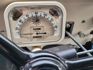
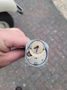
Ever since I bought my 1950 11BL, the clock has been telling me that it is 2 minutes past 2. While this is technically right twice a day, it is not terribly helpful in getting me to the pub on time.
Asking around other more seasoned Traction owners, it seems that it is quite rare to find a Traction with a working clock. The clock mechanism is a fascinating piece of electro-mechanical design, using standard clockwork components to drive the hands but, instead of a wind-up spring driving the mechanism, it uses a solenoid coil to give a little magnetic “kick” to the balance wheel on every tick of the clock, which keeps the clock running. The coil is energized by a tiny pin attached to the balance wheel that makes/breaks a contact each time the balance wheel turns. This happens 5 times every second. Over time, the contacts become corroded, and the clock stops working. Reading-up on the subject, I learned that it is sometimes possible to clean the tiny contacts, but this is rarely a long-term fix. Another possible cause of failure in these clocks is that the very fine wire used inside the magnetic coil can break or, if the car has been converted from 6V to 12V operation, the coil can eventually burn-out.
I did a bit of Googling, looking for someone who might be able to repair my clock, and stumbled across the website of Clocks 4 Classics; they offer a repair kit for Smiths and Jaeger clocks as fitted to a wide range of classic cars (Smiths and Jaeger use the same mechanism under the covers). Looking at their website (clocks4classics.com) they list a wide variety of cars that the kit is suitable for, including Slough-built Traction Avant models, but they did not list the Paris-built cars. Chatting via email with Mark Willows at Clocks 4 Classics, he explained that their fitting list is based on the vehicles that his customers have ordered kits for and, at that time, all the kits they had sold for the Traction Avant had been for UK cars. This intrigued me, knowing that the Jaeger clock mechanism should be more-or-less the same as the Smiths one used in Slough-built cars, so I ordered a kit and set about seeing if it could be made to fit a Paris-built car.
There are some small (but important) detail differences between the clock from my 1950 BL and the Smiths/Jaeger mechanism that the kit was designed for. Clocks 4 Classics have excellent fitting instructions which can be downloaded from their website, together with several videos on YouTube showing the process of dismantling, cleaning, and then reassembling a clock using the repair kit. What follows is a step-by-step record of the rebuilding of my clock, and I will highlight where things depart from the standard Clocks 4 Classics instructions.
Removing the clock from the speedo binnacle.
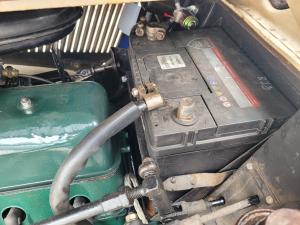
When undertaking any electrical work on a car, it is good practice to first disconnect one of the battery terminals. This is especially important when removing the clock because it is on a permanent feed and, consequently, at battery voltage at all times. The last thing you want is to accidentally short it to ground while working on the dashboard and burn the wire out (or worse).
Release the speedo drive from the back of the speedo unit by reaching up under the dashboard and undoing the knurled collar which holds the drive in the speedometer.
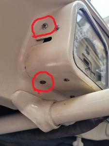
Undo the 4 screws that hold the binnacle in the dashboard – there are 2 on the bottom and one on each side.
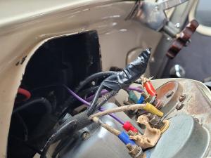
Pull the binnacle away from the dashboard and undo the feed to the clock. If you intend to use the car while the clock is out for repair, it is important to make this wire safe so that it cannot come into contact with any metalwork or any other wire and cause a short circuit. I recommend wrapping the end of the wire in insulating tape.
Undo the 2 screws holding the clock in place. To avoid losing these screws while the clock is out of the car, you may want to screw them back into the holes they came out of, but be careful not to drop them through the hole where the clock face used to be – it is a right pain to try to retrieve them from the front of the speedo assembly – ask me how I know!
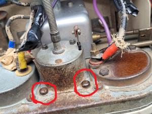
You can now remove the clock from the binnacle – the clock adjusting cable just slides out of the side of the binnacle.
Disassembling the clock.
Some of the clock components are tiny and would be very easily lost if dropped on a garage or workshop floor. I recommend starting with a scrupulously clean workbench, and lay a sheet of white paper on it so that you will be able to see where tiny pieces land when you drop them (and you will drop one or two of them). Also have a suitable container to hand to put the pieces in as you remove them from the clock so that they do not get lost.
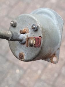
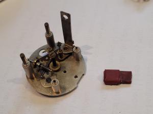
To remove the clock mechanism from the outer casing, remove the screw and clamping plate from the top of the terminal post, then undo the two nuts and one screw from the back of the clock. This is the first point of departure from the written instructions – the clock being dismantled in the instructions and in the YouTube videos has 4 nuts securing the back on. Do not touch the grub-screw in the middle – this is the screw for calibrating the clock if it is running fast or slow.
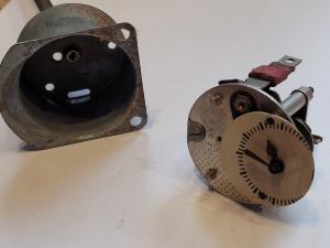
You can now ease the clock mechanism from the outer casing by gently pressing on the ends of the two threaded studs that you have just removed the nuts from.
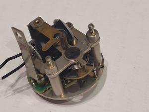
The order of disassembly is not important, but obviously some parts have to be removed before you can access other parts deeper in the mechanism. As you disassemble the clock, take your time to understand where each component goes, and which screws/nuts are used to mount it – this will save a lot of head-scratching when you come to reassemble the clock later. I kept a photographic record of each stage of the process, and not just because I was planning to write this article!
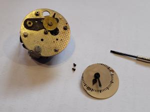
Remove the clock face assembly by undoing the two tiny screws on the edge of the dial and sliding the assembly off its mounting pin and put it to one side. Then slide the minute gear wheel off its mounting pin.
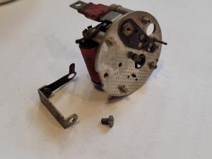
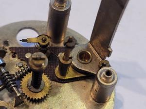
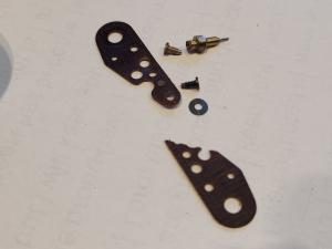
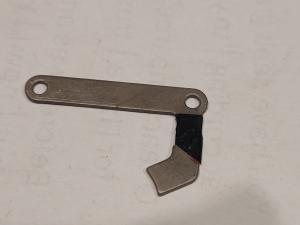
Staying on the front of the mechanism, remove the screw that holds the rear bracket in place. This bracket does not feature in the written instructions or on the YouTube videos. It provides the third mounting point for the screw on the outer casing. Also attached to this bracket is a shaped brass strip that serves as a spring to release the adjustment mechanism from the main drive shaft.
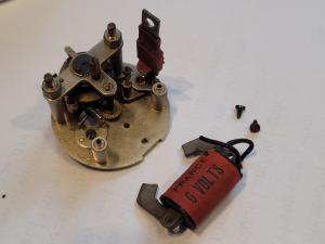
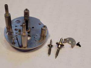
The next step is to remove the solenoid coil. This is slightly different to as depicted in the written instructions where the solenoid is held down by two extension pillars which provide the other two mounting points for the outer cover. In my clock the solenoid is held down by two screws. Snip the two wires as close as possible to where they join the clock mechanism, then undo the two screws and ease the solenoid out.
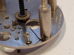
Next, remove the balance wheel assembly. Undo the two nuts that hold down the T-shaped balance support bracket, and lift away the bracket and balance wheel as a single assembly. Extreme care must be taken to avoid damaging the delicate hairspring that joins the balance wheel to its support bracket. Note the position of any spacers/shims under the balance support bracket – they will need to be put back in the same place on reassembly or the balance wheel may not spin freely. My clock had a brass shim on each pillar.
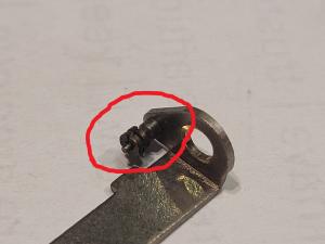
We now come to another component that differs slightly from the Clocks 4 Classics instructions: the connecting bracket. This is the insulated part that the power feed is connected to and passes through the outer casing. In the written instructions and videos it is attached to the top of the connecting pillar by a screw whereas in my clock the top of the connecting pillar was peened over, riveting the connecting bracket in place. Slide the plastic insulator off the connecting bracket (mine was quite stiff but came off eventually), then drill out the rivet in the top of the connecting pillar to release the connecting bracket and the other parts on the connecting pillar. The only part that we need to keep is the connecting bracket itself; the other parts will be discarded.
Now we remove the insulation plates. Undo both screws and remove the top and bottom insulation plates. The only parts we will be re-using are the lower insulation plate and the small black screw. Note that the lower insulation plate has a tiny bearing cap embedded in it for the balance wheel bearing; be very careful not to lose this part.
Undo the screw that retains the double support plate, and then remove the escape wheel and transverse wheel assemblies.
The final step in disassembly is to remove the damper spring. This spring applies a small amount of drag on the escape wheel axle so that it only turns when being driven by the balance wheel.
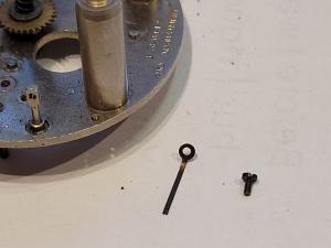
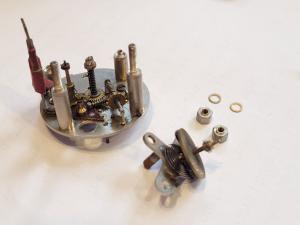
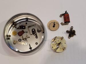
Here is the clock fully disassembled, and ready for cleaning.
Cleaning the mechanism
Clean and degrease all the components using either clock cleaning solution or isopropyl alcohol. Pay particular attention to the bearing holes for the balance wheel, escape wheel and transverse wheel assemblies; the instructions from Clocks 4 Classics suggest using a sharpened cocktail stick to make sure the bearing holes are completely clear. I also took the opportunity to clean 75 years’ worth of grime from the dial face using a cotton bud dipped in isopropyl alcohol.
Preparing for reassembly.
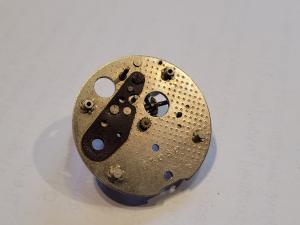
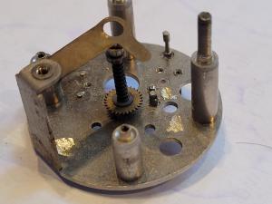
Before starting the reassembly, we need to make a couple of small modifications to the clock’s baseplate. The version from my car has two small locating lugs which do not appear in the instructions from Clocks 4 Classics; these need to be filed/ground off so that the circuit board can sit flat on the baseplate. Similarly, the screw which retains the rear bracket to the baseplate has to be filed flush with the baseplate, otherwise it will also foul the circuit board.
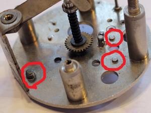
After 5 minutes with a Dremel mini-grinder they are gone. It is important, after filing or grinding these parts of the baseplate, that you thoroughly clean the baseplate and bearings again to make sure that all brass filings are washed away before starting the reassembly.
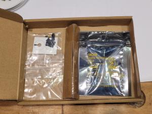
The kit from Clocks 4 Classics is really well thought-out with every bit you might need (with the exception of something to replace the connecting pillar that we had to drill out earlier). There are two bags in the kit; one contains the circuit board, and the other has all the other parts.
If, like me, you had to drill out the end of the connecting pillar, you will now have to sort out a replacement. Mark at Clocks 4 Classics has some spare connecting pillars and screws for sale, or you can make your own (as I did) from a M3x12 brass screw and nut. You can use a longer screw if you don’t have a 12mm one to hand but you will have to cut the threaded portion down to between 11.5mm and 12mm long; clearance under the solenoid pole-piece is very tight (see later) with only about 0.5mm to spare and if the end of the screw touches the pole-piece it will cause a short-circuit. In the kit, there is a piece of heat-shrink tubing supplied to make an insulator over the connecting pillar, so we need to fit this over the screw.
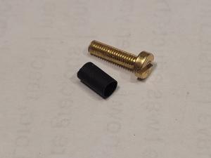
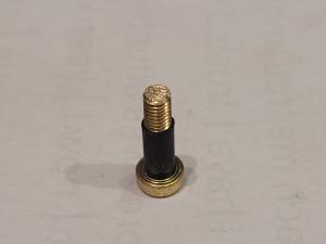
Trim the sleeve down to around 7mm long (it’s not a critical measurement – it just needs to be long enough to prevent the threaded part of the screw touching the baseplate or the underside of the circuit board), and shrink it onto the screw. I did this by standing the screw up on its end on a piece of scrap wood with the heat-shrink sleeve dropped over it and then holding a soldering iron on the end of the screw. After about 20 seconds, the sleeve shrinks onto the screw threads.
You may have to ease the hole in the lower insulating plate to allow the screw with its insulating sleeve to pass through. This can be done with a 3.5mm twist drill or with a small round file.
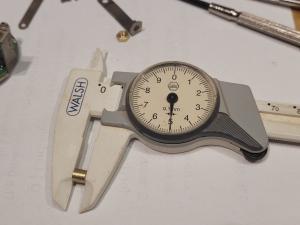
There is a brass spacer in the kit which holds the connecting bracket away from the circuit board to allow space for one of the connections for the solenoid. This was 6.3mm long in my kit. I found it needed to be shortened to 5mm to avoid the top of the connecting pillar causing a short-circuit on the solenoid pole-piece.
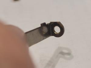
One final modification is required to the connecting bracket: there is part of the old contact mechanism attached to the base of the connecting bracket – this needs to be cut off to allow clearance under the solenoid pole-piece.
Installing the repair kit and reassembly.
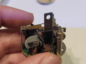
It’s now time to start the reassembly of the clock, following the instructions provided by Clocks 4 Classics. Start by refitting the lower insulator plate (including the bearing cap embedded into it) and secure it in place with one small screw right at its tip. Then fit the transverse wheel assembly, together with the circuit board and connection pillar + connection bracket. I found refitting the damper spring was the fiddliest par of the whole job – it is held in place by the tiniest screw I have ever seen!
The next step is to refit the solenoid coil. The one fitted to my car was a 6V coil, but the car has subsequently been converted to 12V operation, so I chose to fit a new 12V coil from Clocks 4 Classics. There are straightforward instructions on how to swap the pole pieces over from your old coil to the new coil, although the instructions refer to two pole pieces and a spacer strip whereas my coil only had the pole pieces. If your car still has 6V electrics, you can re-use your old coil (assuming that it still works – again, Clocks 4 Classics provide straightforward instructions on how to test the coil) but Mark will have to make a modification to the circuit board before shipping the kit, so make sure that you specify it is for a 6V car when ordering. Mark writes: “We very rarely see 6V clocks and the repair kit is designed for 12V. There is a mod I can do to the circuit board to allow it to work on 6V clocks but before going any further I would suggest that you check that the solenoid is OK as I don’t have any replacements for these.”
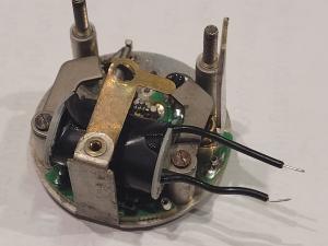
There is only about 0.5mm clearance between the top of the connecting pillar (when using the nut and bolt conversion as I have done) and the pole-piece. If these two components touch, then it will cause a short circuit since the connection pillar is at battery voltage while the rest of the clock’s metal components are grounded. While it is not strictly necessary, I chose to fit a small piece of electrical insulating tape to the underside of the pole piece to make absolutely certain that these components cannot cause a short.
Then, after fitting the sticker onto the underside of the balance wheel as detailed in the instructions from Clocks 4 Classics, refit the balance wheel assembly to the clock, making sure that you refit any shims that you removed earlier. It should move freely and not bind or stick at any point.
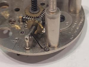
After refitting the solenoid and pushing its wires into the connection points on the circuit board, you are ready to bench-test the clock mechanism as described in the instructions from Clocks 4 Classics; it is really satisfying to see the balance wheel kick into life and the escape wheel start ticking round.
I left it running like this for 15 minutes and checked that the central shaft had rotated through 90 degrees (you can see this by looking at the end of the shaft where the adjuster connects) to confirm that everything was working as expected.
Assuming that the bench test worked successfully, you are ready to refit the minute wheel and the face to the front of the clock.
Before putting the clock mechanism back in its outer casing you will have to fit the insulator over the connecting bracket to stop it causing a short-circuit where it passes through the back of the case. The original plastic spacer will no longer fit without modification because the brass spacer on the connection pillar holds the connecting bracket nearer the back of the case than it was previously. Clocks 4 Classics have foreseen this issue and supply a piece of heat-shrink sleeve in their kit to fit over the connecting bracket in place of the plastic insulator.
One final bench test, and you will be ready to fit the clock back into the car. When I ran a bench test over 12 hours, I found that the clock had lost about 2 minutes, so I adjusted the calibration screw on the back, to make it run a little bit faster, and ran it for another 24 hours to satisfy myself that it can keep time accurately.
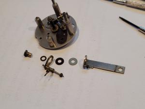
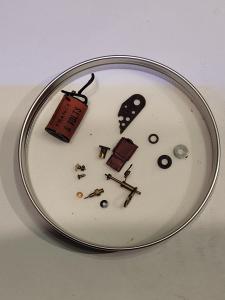
Normally, if you have parts left over after a project, it is a sign that you’ve missed something out during the rebuild, but in this case these are the parts associated with the old electro-mechanical trigger that I have replaced by the solid-state electronic kit from Clocks 4 Classics..
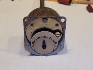
As it says in the best repair manuals – refitting the clock to back of the speedo, and fitting the binnacle back into the car is the reverse of removal (but you swear in different places). Here is the clock back in my car and telling the right time. Now I have no excuse for arriving late to club meetings!
I am grateful to Mark Willows at Clocks 4 Classics for his help and advice in making this successful repair/conversion.
Total expenditure:
Smiths/Jaeger clock repair kit (Clocks 4 Classics): £69*
12v coil (Clocks 4 Classics): £35*
Isoproyl Alcohol (Amazon): £5.70 for 500ml which is more than enough
M3x12 brass nut bolt and washer (eBay) £2.69 for a pack of 5
*If the repair kit and 12v solenoid coil are bought together, Clocks 4 Classics offer the combined kit for £95. Prices correct at the time of writing.
© Paul Bodiam. December 2025
19th April 2026 at 6:25 pm #38063Chris
ParticipantThanks for this Paul.
I will have a crack at this myself later this year – possibly.
Chris
-
AuthorPosts
- You must be logged in to reply to this topic.